Cheap Wall Sconce Conversion - Part 2, The Software
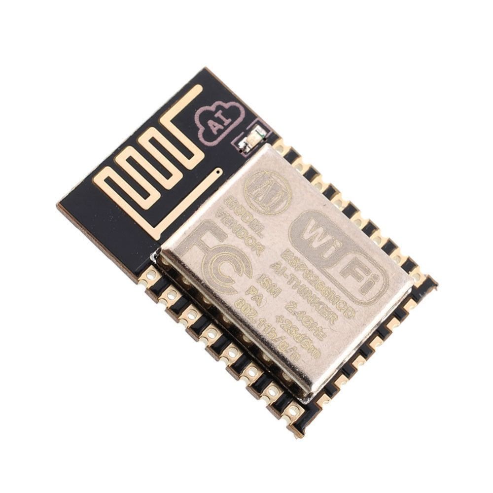
Continuing my post in part 1, now we will look at the software side of things. As I mentioned, the heart of the controller is the ESP8266. It is a very popular MCU used in many IoT applications. There are many SDKs available to choose from to program these things like NodeMCU (a LUA based firmware very popular with those who want to work with something like javascript), an official SDK from the manufacturer Espressif, and Arduino (the popular project for using hardware/software with the physical world).
I chose Arduino because it seemed to run faster and use less resources than NodeMCU while being simpler to work with than the official SDK. There are already a lot of firmware out there that is ready to manipulate for our needs. For my projects, I like to use Espurna. The person who develops it has included a lot of what I need:
-
A nice web page to configure everything.
-
FauxMo support which allows a device to emulate a Belkin WeMO switch. This allows it to be detected by Amazon's Echo for Alexa commands.
-
a REST API to get status and turn it off/on
-
MQTT support for home automation hubs that support it.
-
Wi-FI config mode on first boot
-
An NTP client to get the proper time and a scheduler to do things on time.
-
A way to update the firmware OTA so you don't have to put the device in flash mode every time you want to update.
It is simply a matter of turning things on and off in the code before building the firmware. You will need:
-
Instructions to configure the IDE and get the latest hardware packages are here.
-
The latest Espurna source code from this page The developer has pre-compiled bin files for the devices that are officially supported. I don't have any of those devices, but you scan still use his code and modify it for any generic ESP8266 device and get all the features you need.
The developer also has instructions on how to install the dependencies in the IDE here.
Next, we want to configure the header files to manipulate the software for our needs. Visit the /code/espurna/config directory and open the arduino.h file and the hardware.h file. In the arduino.h file, uncomment the first definition:
define NODEMCU_LOLIN
This allows us to build for that version. Now, I don't exactly have that device, but it is one of the simplest devices (one relay only) and it is at the top of the list. So, it makes things easy. :)
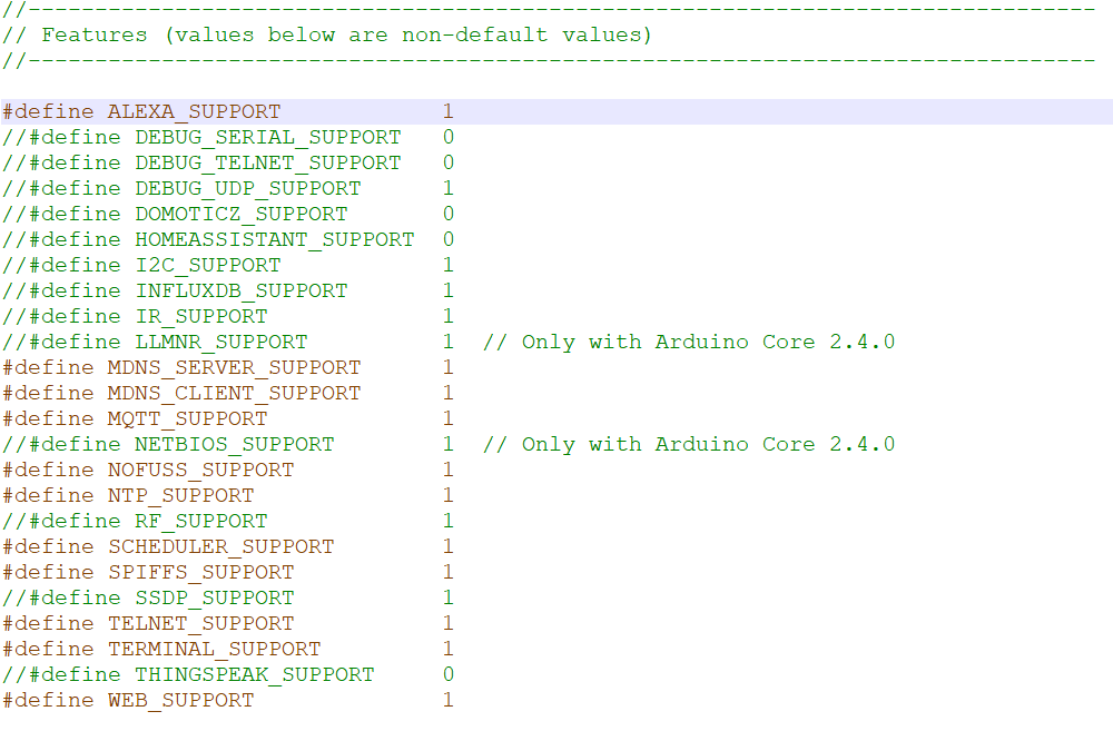
Next, visit the bottom of the header file to view all the features. To include a feature, simply uncomment the feature and set the value to 1.
In the hardware.h file, alter the section at the top for NODEMCU_LOLIN. Since my device doesn't have any buttons, I simply comment out the button section. For the relay, the LinkNode R1 relay is triggered by GPIO 16. So, change the 12 to 16. Everything else can be kept the same. If you have more relays hooked up, you can add more by simply adding more RELAY'n'PIN and RELAY'n'TYPE lines.
After you save the files, finally open up the Arduino IDE. At this point, you should be able to run the verify/compile command. If all is good, it should compile with no errors.
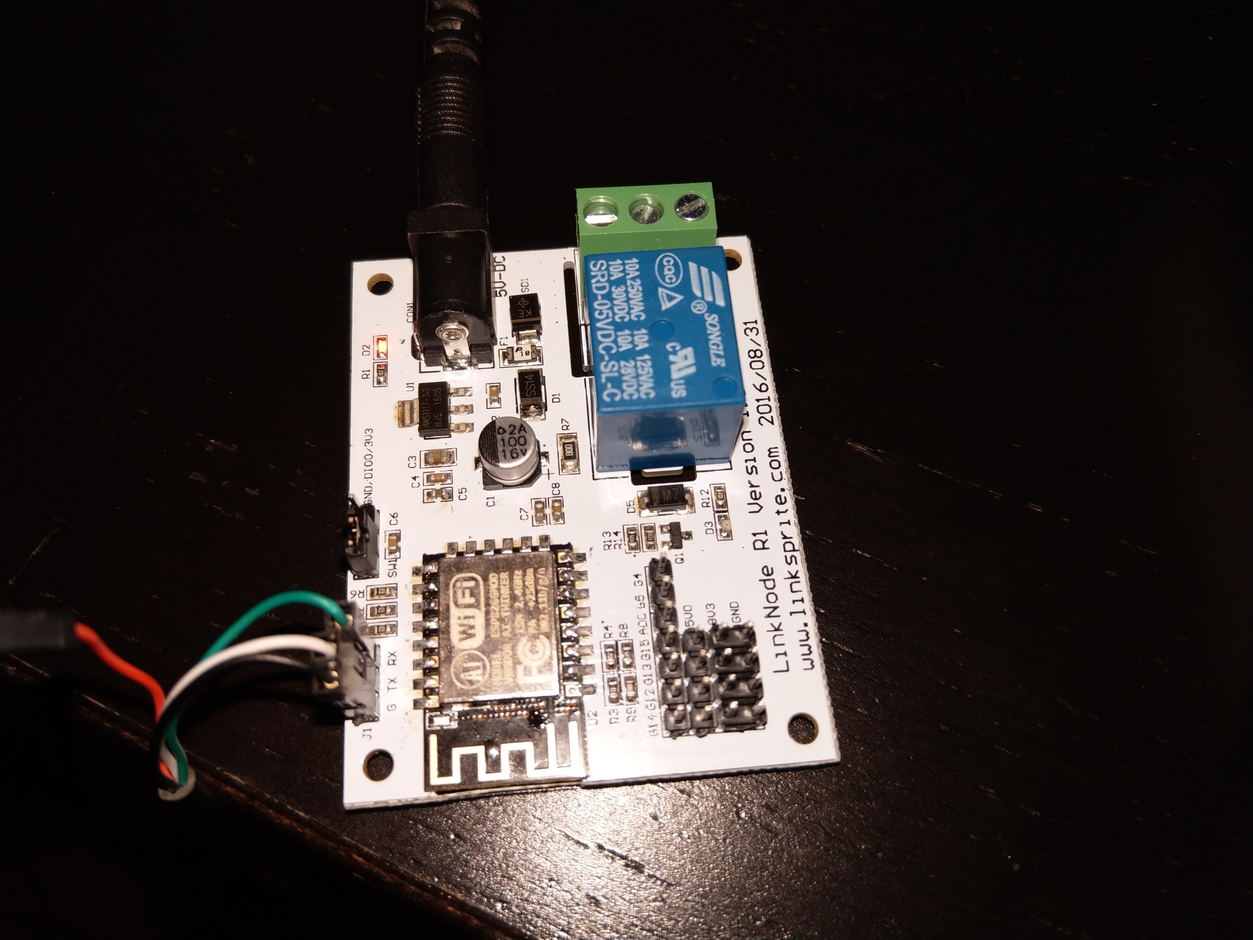
Now, to put the ESP8266 in upload mode, there is a simple jumper on the LinkNode R1. The ESP8266 has a simple upload mode that is triggered when you pull certain pins to ground (DIG0) in this case. Of course, this particular module I'm working with to show as an example had an issue that required me to resolder some things on this "integrated" board. Ugh - that was the whole point of me buying one of these! To not have to do any major hardware stuff. Anyway, troubleshooting ESP8266 hardware is another blog post for another day. In addition to the jumper, you need to hook up a USB serial cable like this one on Amazon
USB cables use a color coding system to indicate voltage, data output, data input, and ground.
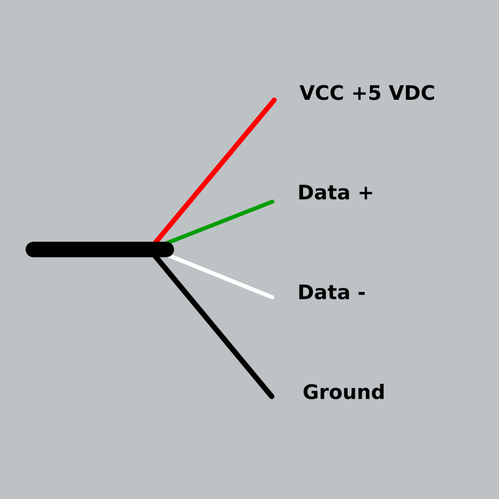
Hook up the ground to ground, transmit to Data -, and receive to Data +. It is not necessary to use the voltage line from the USB cable as power will be provided by the 5v barrel connector.
With the device in upload mode, a simple press of the "Upload" button in the Arduino IDE will write the software to your flash.
After the flash, cut the power, return the jumper to normal. When it boots up, you can now configure Espurna as it will present a Wi-Fi AP. Instructions on what to do can be found here.
Once configured, you now get a fancy web interface to configure this thing.
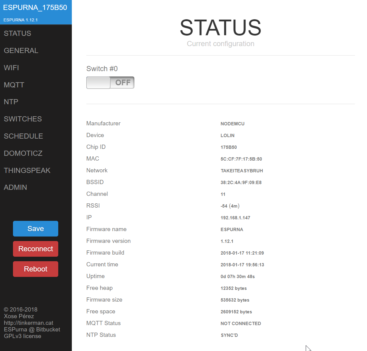
On the left side, you should see features chosen in the arduino.h file. You can set things up like connecting to your existing wi-fi network, hostname, schedules, NTP, etc.
Important features:
-
Alexa integration found under General. The hostname is used as the device name during Alexa discovery.
-
REST API key can be found under the Admin section. The API is controlled via requests to endpoints that look like this:
http://hostname/apis?apikey=C62ED7BE7593B658 (this returns available switches and sensors)
A full API reference is here. You can basically read the status of the relay and change it through this interface. This is great for home automation and I use it with Kodi callbacks mentioned in a previous post. I'll have to write up how to get Kodi callbacks working next.
- Finally, a last great important feature is the ability to update the firmware through the web interface. Now that you have the base firmware in there, if you build newer firmware with Arduino, you can simply upload the .bin file through the web interface for future updates. This removes the need to do USB/serial flashing each time you want to update this darn thing.